This blog post provides a comprehensive overview of repair strategies for metal additive manufacturing (AM) technology. It explores repair techniques available for Meltio’s technology AM and emphasizes the importance of selecting appropriate repair strategies based on the specific defect types, material properties, and application requirements.
Lastly, it addresses the challenges and considerations associated with implementing repair strategies for metal AM. By adopting an AM repair strategy, manufacturers can enhance cost savings.
Additive Manufacturing Repair Overview
Repair applications for metal 3D printing involve utilizing advanced techniques to restore or enhance damaged or worn-out metal parts using additive manufacturing processes. They can be categorized into two main areas: part restoration and part modification.
In part restoration, the goal is to repair damaged or degraded metal parts, extending their lifespan and avoiding the need for costly replacements. Part modification involves enhancing existing parts by adding additional features or improving their performance characteristics.
Repair applications for metal 3D printing offer several advantages over traditional repair methods. They enable complex geometries to be repaired with minimal material waste and reduced lead times, and also offer the possibility of performing tasks with a safer and more controlled process.
Additionally, the repaired parts can exhibit equal or even improved mechanical properties compared to the original part, thanks to the fine control over material deposition and the potential for using advanced alloys.
Wire-Based Laser Metal Deposition (W-LMD) repair is an advanced and innovative technique that offers a range of significant advantages for restoring and repairing metal components. Through the precise application of laser-generated metal deposition, this method has revolutionized the field of metal repair. Nonetheless, there are also challenges to be considered.
These include the need for skilled technicians who can assess the damage accurately, design the repair strategy, and operate the 3D printing equipment. Material compatibility, process optimization, and quality control are also critical factors that need to be carefully managed to ensure successful repairs.
Repair Process in AM
The repair process in metal additive manufacturing refers to the sequence of steps involved in restoring or fixing a damaged metal component using additive manufacturing techniques. This process typically includes the following stages:
1. Inspection and Assessment: The damaged part is thoroughly inspected to determine the extent of the damage and assess its repair feasibility. An analysis of the geometry is done in order to identify cracks or defects and also to understand the material properties.
2. 3D Scanning: In many cases, it is necessary to 3D scan the damaged part to create a digital model of its current state. The scanned data serves as the basis for designing the repair strategy.
3. CAD Modeling: A Computer-Aided Design (CAD) model is created or modified based on the scanned data. The model is adjusted to incorporate the repair geometry while ensuring compatibility with the surrounding structure.
4. Repair Definition: The repair strategy is defined, including considerations for the choice of additive manufacturing technology, material, layer thickness, and orientation. This planning aims to achieve optimal mechanical properties and accurate deposition.
5. Material Selection: The appropriate metal alloy is chosen for the repair, taking into account its compatibility with the original material and the desired mechanical properties of the repaired part.
6. AM Repair: The actual repair process involves using a metal additive manufacturing machine to deposit material layer by layer onto the damaged area. The deposition process is carefully controlled to achieve the desired structural integrity.
7. Post-Processing: After the repair is complete, post-processing steps are performed to improve the surface finish and mechanical properties of the repaired area. This includes heat treatment, stress relief, and finishing processes.
8. Inspection and Quality Control: The repaired part is inspected to ensure that the repair was successful and meets the required standards. Non-destructive testing methods, such as X-ray, may be used to verify the quality of the repair.
9. Certification and Documentation: The repaired part may undergo certification processes, especially in industries with strict quality standards. Detailed information on the repair process, material used, and quality control measures should be documented.
10. Reintegration: The repaired part is integrated back into the original assembly or system, restoring its functionality.
2.1 Advantages of Additive Manufacturing Repair
The manufacturing industry has witnessed a revolutionary transformation with the advent of additive manufacturing, which has introduced innovative production solutions. In the field of repairs, additive manufacturing, particularly with Wire-DED systems, presents numerous notable advantages compared to conventional repair methods.
- Cost-Effectiveness: Repairing parts using additive manufacturing can be highly cost-effective. Traditional repairs often involve manual processes which can be time-consuming and expensive. Moreover, DED systems, as Meltio’s technology, allow for precise repairs by adding material layer by layer, minimizing waste and reducing the need for additional tooling or extensive machining. This can result in substantial cost savings.
- Design flexibility: Additive manufacturing enables unprecedented design freedom. When repairing parts, traditional methods often require conforming to the original design, which may not be optimal for repair purposes. Additive manufacturing allows for the creation of customized designs tailored to address the repair requirements. This flexibility enables the repair of complex geometries and the incorporation of enhanced features or reinforcements, leading to better performance and durability.
- Reduced lead time: Repairing parts traditionally can involve prolonged lead times due to the need to source replacement components or wait for specialized equipment and skilled labor. Additive manufacturing can significantly reduce these lead times by eliminating the reliance on extensive supply chains.
- Accessibility and decentralized repairs: Additive manufacturing has the potential to decentralize repair capabilities, making repairs more accessible and efficient. With Meltio’s technology, individuals and organizations can perform repairs in-house, reducing the need to outsource repairs or rely on specialized repair facilities. This accessibility can lead to faster turnaround times, reduced transportation costs, and increased independence in maintaining and repairing equipment.
- Consistency: Repair applications with metal 3D printing are automated and therefore enhance the gain in operability. The system follows pre-programmed instructions, eliminating human error and variations that may occur in manual processes. This results in high-quality and repeatable repairs, ensuring consistent performance of the repaired components.
- Safety: The ability to repair complex components with precision minimizes the risk of improper fits or compromised structural integrity, therefore there is a reduction of injuries associated with manual repair processes.
Traditional Welding Repair Methods
Welding is used to join damaged pieces or fill cracks and defects and is one of the most common methods for repairing metal parts. Welding is performed by melting a filler metal compatible with the base metal, creating a strong bond between the two parts.
3.1. Types and disadvantages
Each welding technique has its own advantages and disadvantages and the choice of technique often depends on the specific requirements of the project, such as the type of material, thickness, and desired weld quality.
1. Shielded Metal Arc Welding (SMAW): utilizes an electric arc between a flux-covered electrode and the workpiece to create a weld joint.
Disadvantages:
- Relatively slow process due to manual electrode changing and arc striking.
- Not suitable for thin materials, as it can cause distortion and burn-through.
- Slag residue requires additional cleaning after welding.
- Limited to flat or horizontal positions due to slag flow.
2. Gas Metal Arc Welding (GMAW or MIG): uses an electric arc between a consumable wire electrode and the workpiece, while a shielding gas protects the weld area from atmospheric contaminants.
Disadvantages:
- Requires a shielding gas, which adds complexity and cost.
- Weld quality can be affected by wind and drafts in outdoor environments..
- Prone to porosity issues if not properly controlled.
- May not be suitable for thick materials in a single pass.
3. Gas Tungsten Arc Welding (GTAW or TIG): utilizes a non-consumable tungsten electrode to create an electric arc and fuse metals together.
Disadvantages:
- Slower process compared to some other methods.
- Requires a high skill level due to precise control of the arc, filler material, and shielding gas.
- Not as suitable for high deposition rates in thick material welding.
- It is sensitive to contaminants on the workpiece, the electrode, or the filler material. Even small levels of contamination can affect weld quality.
4. Submerged Arc Welding (SAW): uses an electric arc between a continuously fed electrode and the workpiece.
Disadvantages:
- Limited to flat or horizontal positions due to the submerged arc process.
- Slag removal after welding can be time-consuming.
- Requires a flux layer, which adds material cost and may contribute to slag-related issues.
- The fixed nature of the SAW process can limit its use in certain joint configurations or hard-to-reach areas.
5. Oxy-Fuel Welding (OFW): uses the heat generated from the combustion of a fuel gas (typically acetylene) and oxygen to melt and fuse metals.
Disadvantages:
- Limited to certain materials, primarily non-ferrous metals, and thin sections.
- Lower joint strength compared to some other welding methods.
- Slower process due to the need to heat the base metal to a molten state.
- Acetylene, the fuel gas commonly used in OFW, is flammable and requires careful handling and storage. It can pose safety risks if not properly managed.
6. Flux-Cored Arc Welding (FCAW): a process that combines aspects of both MIG (Metal Inert Gas) welding and stick welding. It uses a continuously fed electrode that has a flux core, which produces the shielding gas and creates a slag that covers the weld pool.
Disadvantages:
- Produces more smoke and fumes compared to some other methods.
- This can result in slag inclusion if not properly controlled.
- The cost of flux-cored wires can add up over time, especially in high-volume welding operations.
- Similar to GMAW, it requires a shielding gas and can be affected by wind.
Repair Procedure with W-LMD from Meltio
The deep control offered by Meltio’s technology allows for precise manipulation of a repair process. This means that it can reach the near net shape, effectively addressing damage or defects in the material close to the surface.
By having such fine control, it ensures that the repaired area achieves the desired density and structural integrity based on the specific materials profiles provided by Meltio.
TIP: Want to know how process control works? Check it out here!
The distribution and calibration of lasers in Meltio’s systems play a crucial role in optimizing the repair process. By directing almost half of the laser energy towards the base material and the remaining half towards the wire (filler material), an ideal balance is achieved.
This distribution promotes the diffusion of both materials, ensuring a thorough integration between the repaired area and the surrounding base material.
The laser energy that is directed towards the base material aids in heating and preparing the damaged area, facilitating the bonding process. Simultaneously, the laser energy directed towards the wire promotes controlled melting and deposition of the filler material, ensuring precise and controlled application.
In addition, the calibrated distribution of laser energy helps to minimize potential issues such as heat distortion or warping in the repaired area. Meltio’s technology mitigates the risk of localized overheating and maintains the overall integrity of the repaired component.
4.1. Meltio Repair Types
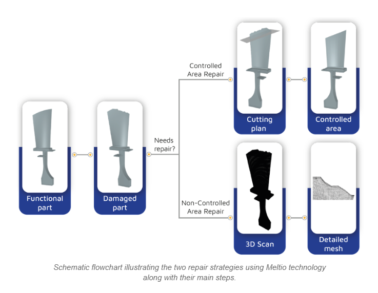
When it comes to repairs using Meltio technology, two distinct strategies come to the forefront: Controlled Area repairs and Non-Controlled Area repairs. The primary distinction between both repairs lies in the approach and challenges associated with each.
Controlled Area Repairs: This involves a more simplified process, beginning with a precise understanding of the required material addition. The repair trajectory is carefully planned, ensuring smooth movements to facilitate the printing process.
This method allows for greater control and predictability, as the repair starts with a well-defined area, previously machined in order to achieve a controlled area, and known material requirements.
Non-Controlled Area Repairs: This method is more complex and intricate. The damaged region is not clearly defined initially, necessitating the use of 3D scanned models to identify the extent and location of the damage.
Once the damaged areas are identified, the challenge becomes determining the most suitable approach to reconstruct the broken area, taking into account the irregular and non-smooth cuts. This requires adapting the filler material to match the unique contours of the damaged region.
In Non-Controlled Area repairs, the printing process must be exceptionally accurate to accommodate the nonlinear and irregular shapes of the damaged area. The printer needs to precisely navigate these intricate contours to ensure a seamless integration of the filler material with the existing structure. Achieving a successful repair in these scenarios demands meticulous attention to detail and a high level of precision.
Since damaged material needs to be removed from the surface of the repair, to ensure suitable material properties at the intersection with the deposited material, it is strongly advised to always perform material removal also in order to bring a Non-Controlled Surface to a Controlled one.
4.1.1. Controlled Area repair
Controlled area repairs are the most commonly utilized method due to their effectiveness in addressing damages. This approach is considered standard practice as it ensures that the affected area is thoroughly cleaned and potential defects are mitigated before proceeding with the repair process.
By following the steps established, the placement of material and other critical factors are well-defined and aligned, resulting in a more straightforward and consistent procedure.
When opting for controlled area repairs, precise surface identification helps to optimize the slicing generation, surface quality and printing stability. Irregular or non-uniform areas may cause the deposition head to undergo rapid reorientations, leading to irregularities during the printing process such as vibrations.
Hence, it is preferable to work with regular and defined areas to ensure a smoother repair process.
The typical procedure for this type of repair can be outlined as follows:
- Identify the damaged area.
- Prepare the cutting/machining process, taking into account the removal of any debris and optimizing slicing requirements.
- Design a suitable holder/fixture (which can often be utilized for both machining and printing processes).
- Machine the part using a subtractive machine (such as a CNC milling machine, a lathe, a grinder among others).
- Apply over thickness in the CAD model and prepare the material that will be added by slicing it appropriately.
- Position the holder and part in place.
- Implement the 3-point calibration method to ensure accurate alignment.
- Adjust the CAD/CAM system to match the real position of the part.
- Prepare the toolpath.
- Begin the repair process.
By sticking to this procedure, controlled area repairs can be executed effectively, ensuring a successful and accurate restoration of the damaged part.
When aiming for high tolerances or low surface roughness, it is recommended to apply over thickness to the filler material used for the repair in order to ensure sufficient material for the post processing. The extent of over thickness required would depend on the geometry of the part, the material being used or the desired level of accuracy. Even though the specific values may vary, an over thickness of 1.5 is the general guideline recommendation.
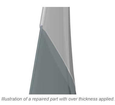
By including this intentional extra material, it offers a margin for subsequent finishing procedures like grinding, polishing or machining in order to attain the intended tolerances and surface finish. These processes involve removing material from the surface and the over thickness compensates for any potential deviations or unevenness that may arise during these operations.
Considering that the surface requiring repair is well-defined, the toolpath generation process becomes a significantly straightforward task, allowing for the generation of smooth toolpaths.
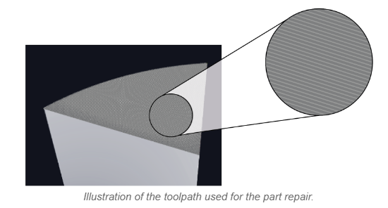
Here are examples of applications for which it is advisable to exclusively opt for controlled area repairs due to the critical nature of the components involved.
- Aerospace Engine Components: Repairing critical aerospace engine parts requires a controlled area to maintain precise metallurgical properties and ensure safety and reliability in high-stress conditions.
- Medical Implants: Repairing medical implants demands a controlled area due to the strict hygiene and quality standards necessary to ensure patient safety and regulatory compliance.
- High-Precision Machinery Parts: Components used in precision machinery or equipment often require repairs in controlled environments to maintain the strict tolerances necessary for proper function.
- Semiconductor Manufacturing Components: Repairing parts used in semiconductor manufacturing processes requires controlled conditions to prevent contamination that could adversely affect semiconductor production.
4.1.2 Non-Controlled Area repair
In certain scenarios, there may be a need to repair areas that lack well-defined boundaries. Fortunately, Meltio’s technology offers remarkable precision and control over the repair process, conceding the adaptation of filler material to accommodate such indistinct areas.
It is essential to establish an initial approximation for the repair and, to achieve this, a 3D scan should be conducted prior to the repair procedure. This scan creates a model that provides an estimate of where the filler material should be applied. The accuracy of this approximation relies heavily on the resolution of the scan, particularly in capturing intricate details of the damaged area.
This repair strategy proves particularly valuable when dealing with broken areas exhibiting multiple split directions. By swiftly adjusting the deposition head orientation, the process can effectively navigate through these complexities. It is worth noting that maintaining stability and ensuring uniformity during the repair process can be challenging due to the rapid reorientations.
By exploiting the capabilities of Meltio’s technology, coupled with precise 3D scanning and adaptable filler material, the repair of poorly defined areas becomes feasible. This approach enables efficient and effective repairs, even in intricate scenarios involving irregular shapes and varying rip directions.
For this repair strategy, the toolpath generation exhibits a lack of smoothness in comparison to the controlled area it intends to replicate.
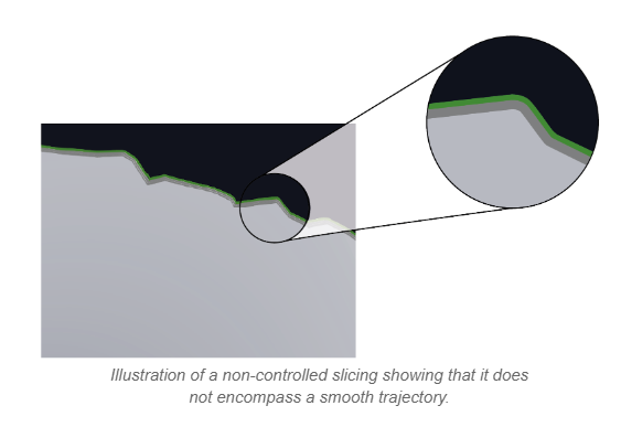
Non-Controlled Area repairs are particularly advantageous for scenarios where component integrity, safety and regulatory compliance are not critical factors.
- Industrial Equipment Housings: Repairing superficial damages on equipment housings, such as those used in manufacturing or construction, might not require the strict environment of a controlled area.
- Agricultural Machinery Components: Repairing certain parts of agricultural machinery, like non-critical structural elements, can be done outside a controlled area, especially when the repairs are not safety-critical.
- Consumer Goods: Repairing metal parts in consumer products like kitchen appliances, tools or recreational equipment can often be accomplished in a non-controlled setting.
- Artistic Metalwork: Repairing minor imperfections on artistic metal creations, sculptures, or decorative items can typically be done without the need for a controlled environment.
4.2. Advantages of W-LMD Repair
By harnessing the power of laser technology and metallurgy, W-LMD not only restores components to their original condition but also enhances their durability and performance. Some advantages that make W-LMD an exceptional choice for repairing metal components are described below.
- Precision and Accuracy: The usage of a laser beam to melt and fuse a wire feedstock onto the damaged area offers a high precision control.
- Minimal Heat Affected Zone (HAZ): The focused laser beam generates localized heat, minimizing the heat-affected zone around the repair area. This reduces the risk of distortion, warping and changes in material properties.
- Enhanced Metallurgical Bonding: The metallurgical bonding achieved in W-LMD is strong and reliable, often surpassing the properties of the base material. This leads to improved mechanical properties and overall component integrity.
- Versatility in Materials: W-LMD can work with a wide range of metal materials, including stainless steel, mild steel alloys, carbon steels, nickel based alloys and titanium alloys.
- High Deposition Rates: It can achieve high deposition rates, enabling faster repairs and reduced downtime for industrial equipment and machinery.
- Reduced Material Waste: Since it is a controlled process that deposits material only where needed, the material waste is minimized, reducing the need for extensive machining post-repair.
- Remote and Inaccessible Repair: It can be automated and performed using robotic systems, allowing for repairs in hard-to-reach or hazardous locations without risking human safety.
- Reduced Downtime: With its efficiency, W-LMD can significantly reduce downtime for repair applications, leading to increased operational efficiency.
4.3. Part Centering and Calibration
One crucial aspect of repairs in additive manufacturing involves proper fixturing for the additive process. In the case of hybrid systems incorporating both subtractive and additive capabilities, the calibration method within the system handles the positioning and alignment, reducing the need for extensive fixturing. However, when it comes to repairs using robotic arms, which lack an internal calibration protocol, fixturing and calibration become critical considerations.
Typically, a specialized fixture is required for robotic arm repairs and the fixture design must be highly precise from the outset, aiming to minimize deviations between the actual scenario and the simulation. This involves incorporating features such as double pins, shoulder screws with collars and reference points for calibration, among others.
Despite meticulous adjustments and well-designed fixtures, there will always be some degree of deviation from the simulation. In certain cases, repairs may not require extreme precision, and a proper fit within the fixture may be satisfactory.
However, it is generally recommended to calibrate the part before initiating the printing process. This is where the significance of reference points comes into play.
The use of reference points is vital for achieving accurate calibration. One common approach is the 3-point method calibration, which involves selecting three corresponding points on both the physical part and the CAD/CAM simulation.
By establishing these points of reference and applying a transformation matrix, the simulation can be adjusted to match the precise placement of the current part. It is important to note that this calibration process should be repeated whenever the holder or fixture is unscrewed and reassembled.
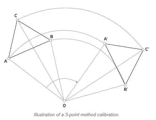
By implementing a thorough fixturing and calibration strategy, repair processes in additive manufacturing can be executed with greater precision and reliability, ensuring optimal alignment between the virtual model and the physical component being repaired.
4.4. Limitations
The limitations for the W-LMD with Meltio are related with the deposition head accessibility and some design constraints intrinsic to the technology.
- Deposition Head Accessibility: It is a crucial consideration since the equipment setup may pose challenges when attempting to repair components with intricate geometries or in confined spaces. Components that have limited openings or complex internal structures could present difficulties in positioning the deposition head without the risk of collision. Ensuring that the deposition head can be properly positioned to access the repair area is essential for successful W-LMD repair.
- Design Constraints: These limitations encompass factors such as minimum wall thickness, minimum slot width, minimum vertical hole diameter, and required overhang angles. Adhering to these considerations is vital to achieve success while effectively utilizing the capabilities of the technology.
TIP: To delve deeper into this aspect, check the Meltio Design Guidelines.
4.5. Repair + Enhancement
The combination of repair and enhancement in Wire-Based Laser Metal Deposition (W-LMD) refers to a comprehensive approach in which not only the original functionality of the part is restored but also its performance and durability can be improved beyond their original state.
In addition to addressing the immediate repair needs, W-LMD offers the opportunity to enhance the repaired part’s characteristics. This can involve various strategies:
- Material Selection: The choice of deposition material can be tailored to enhance specific properties such as wear resistance, corrosion resistance, or thermal conductivity, depending on the application requirements.
- Surface Coating: The repaired area can be coated with materials that provide superior protection against external factors improving the part’s longevity and performance.
- Strengthening: By adjusting deposition parameters, the repaired area can be made stronger than the original, contributing to the part’s overall strength and load-bearing capabilities.
- Structural Modification: Design alterations can be introduced during the repair process to enhance the part’s structural integrity or optimize its performance in a given application.
- Functional Upgrades: Through precise deposition, functional features or modifications can be added to the part, a process referred to as Feature Addition. This makes the part more versatile or better suited to its operational environment.
By integrating these enhancement aspects into the repair process, W-LMD technology offers a comprehensive approach to maintaining and upgrading metallic parts. This combination of repair and enhancement maximizes the value of the technology, extending the lifecycle of components while optimizing their performance for various applications.

