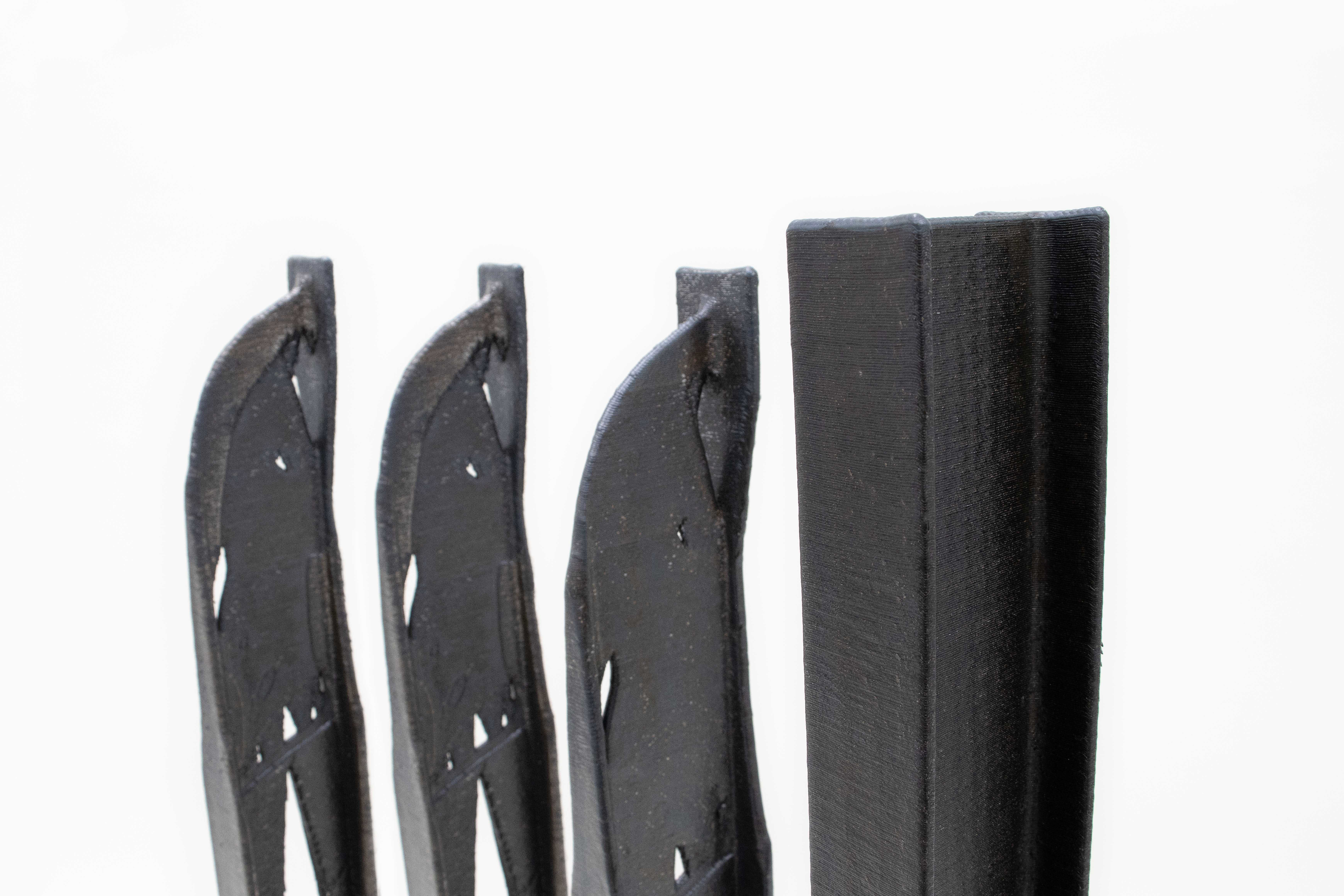
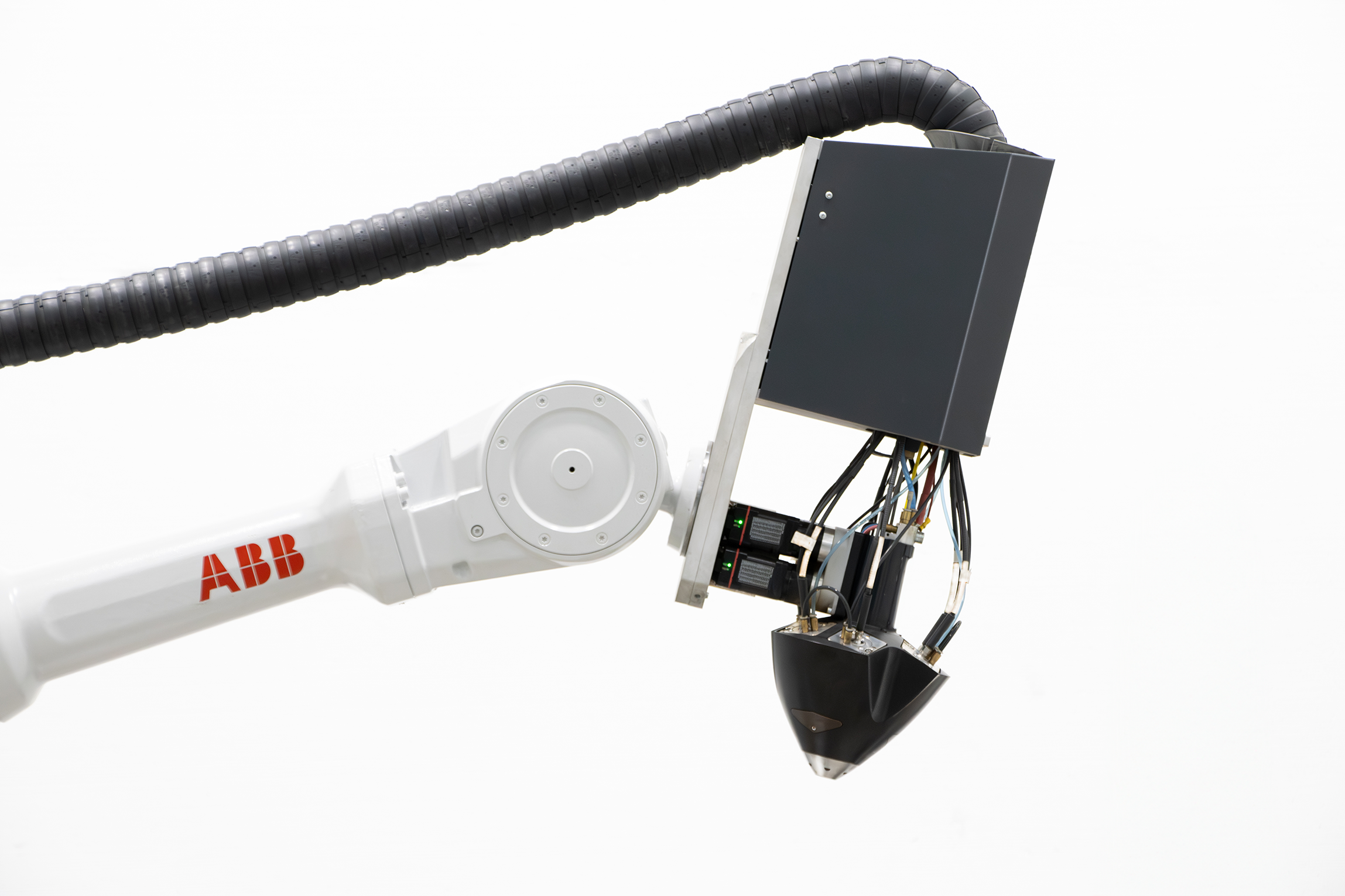
Robot arm 3D printing, also known as robotic 3D printing or robotic additive manufacturing, combines a 3D printer head that extrudes materials with a multi-axis robotic arm, resulting in a highly versatile 3D printer compared to traditional models.
The utilization of a robotic arm with its extensive range of movement makes it well-suited for large-scale projects. Furthermore, robotic arm 3D printing often eliminates the need for support, enhancing design freedom and reducing material costs. In this approach, self-supporting structures are necessary, which typically exclude overhanging designs.
However, manufacturers have found solutions to this limitation by enabling the reorientation of the building platform. This capability allows for the creation of overhangs by aligning the extrusion layer with the underlying geometry, effectively utilizing it as a support.
Robotic arm metal 3D printing offers numerous benefits and, in spite of that, it is important to be aware of its limitations. Understanding geometric restrictions, clearance impediments, and size constraints will pave the way for further advancements in this field.
By knowing these limitations, the users can make informed decisions and can navigate potential challenges more effectively when implementing robotic arm 3D printing.
Benefits of Robotic Arm Metal 3D Printing
When it comes to robotic arm metal 3D printing, the possibilities for creating intricate and complex geometries are truly remarkable. The technology offers a unique advantage by allowing precise control over toolpath trajectories, which can be adapted to meet the specific requirements of the geometry being printed.
The robotic arm used for metal 3D printing, with its six degrees of freedom (DOF) that can be coupled with the potential addition of two external axes, provides an extensive range of slicing solutions for a given part.
The versatility of robotic arm 3D printing lies in its ability to maneuver the deposition head in a way that traditional 3D printers cannot. By leveraging the extra degrees of freedom, the printer can effectively navigate around obstacles, overhangs, and intricate features with enhanced precision. This capability opens up new possibilities for designing challenging and organic shapes that were previously difficult to manufacture using conventional methods.
Moreover, the ability to control the orientation and angle of the deposition head allows for optimized layer deposition and improved structural integrity. This feature enables the printer system to create overhangs and unsupported structures more effectively, reducing the need for excessive support structures and minimizing material waste.
By intelligently adjusting the toolpath trajectories to suit the geometry, the robotic arm 3D printer can produce parts with greater accuracy, intricacy, and strength.
The potential integration of external axes further expands the capabilities of robotic arm metal 3D printing. These additional axes can be utilized for specialized functions, such as rotating the part during the printing or interpolating an external arm to keep the deposition head printing vertically, taking advantage of the gravity that favors the attachment of the deposited material and the previous layer.
This flexibility empowers designers and engineers to explore innovative slicing strategies and printing techniques to achieve the desired results for their specific applications.
Robotic Arm Metal 3D Printing Limitations
Robotic arm metal 3D printing is renowned for its adaptability and versatility, enabling the creation of a vast array of parts. However, like any manufacturing process, it is essential to recognize the limitations that come with it. There are specific considerations and challenges associated with this technology that will be explained hereinafter.
In the following topics, a review of the geometrical limitations of the part to be printed is provided with detailed guidelines and recommendations to ensure successful prints within these limitations.
It also emphasizes the boundaries derived from the equipment dimensions, informing how to avoid collisions between the deposition head and the printed object, with valuable insights on optimizing tool paths to mitigate the risk of damage.
Furthermore, it addresses the constraints of the printing volume within the Meltio system, enabling users to optimize their designs and efficiently utilize the available space.
Meltio Guidelines
The Meltio Design Guidelines provide an overview of the existing constraints associated with laser wire deposition technology. These limitations outline the specific aspects that warrant attention and consideration.
TIP: To delve deeper into this aspect, check Meltio Design Guidelines Whitepaper.
3.1. Thin Walls
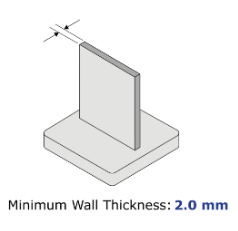
The minimum wall thickness is related to the wire diameter and the material. As a generic value for 1.0 mm diameter wire, the minimum wall thickness would be 2.0 mm.
If the model has thinner walls, the CAD model needs to be modified to add material to reach the required minimum wall thickness. This added material will be removed during post processing.
3.2. Minimum Slot Width
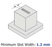
Represents the minimum separation between two vertical surfaces that remain without contact when printed. The minimum slot width is 1.2 mm.
Parts printed with larger layer heights require larger separation between the surfaces to avoid contact due to their increased surface roughness.
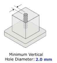
3.3. Minimum Vertical Hole Diameter
Same as slots, printing holes at non-vertical angles requires additional separation between the two surfaces. The minimum vertical hole diameter free of obstructions is 2.0 mm.
Parts printed with larger layer heights require larger separation between the surfaces to avoid contact due to their increased surface roughness.
3.4. Teardrop Profile
Holes perpendicular to the tool orientation, as it can be horizontal holes while the tool is printing vertically, cannot be printed with a round profile as they form a very steep overhang and bridge at the top.
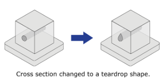
Changing the cross section to a teardrop shape reduces the maximum overhang angle to a manageable degree. This option is suggested if horizontal holes or cooling channels are unavoidable and cannot be accessed for machining in post processing.
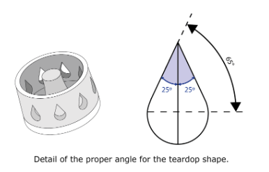
The teardrop shape offers adaptability by preserving the channel section, ensuring a continuous flow reminiscent of the round shape. Alternatively, it can be reimagined to fit within the inscribed circle of the round shape and subsequently undergo machining for precision. The recommendation is to have overhangs to an angle of 65° or above from the horizontal plane.
3.5. Over thickness for post processing
When modifying a design for robotic arm metal 3D printing, it is crucial to take into account the technology’s inherent near net shape (NNS) outcomes. Therefore, the geometry of the design should be appropriately adjusted to align with this characteristic.
Meltio’s wire LMD is a near net shape technology since it enables the printing of a model that closely approximates the size and shape of its final version. Therefore, it is essential to apply over thickness in order to be able to achieve the net shape after the post processing operations.
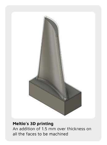
By incorporating over thickness, extra material is provided, ensuring that post processes can be carried out without compromising the final dimensions of the part. The process of applying over thickness for the parts to be printed using Meltio’s technology typically involves modifying the original 3D design of the part and this adjustment can be made using CAD software or other design tools. It is recommended to add 1.5 mm of extra stock wherever the final surface requires accuracy and low roughness.
3.6. Materials
The material choice in robotic arm metal 3D printing plays an important role in determining the printability, process parameters, mechanical properties and post-processing requirements. It is important to carefully consider the material’s characteristics and compatibility with the Meltio technology to achieve successful and optimal results.
The behavior of materials in their molten state can vary significantly, leading to diverse outcomes during the printing process. Consequently, geometries that print effectively with materials possessing specific viscosities when in a liquid state may yield less favorable results with metals of lower viscosity, and vice versa.
Currently, the Meltio materials encompass a broad selection of metals that have been thoroughly verified, ensuring their stability during the printing process.
Constraints imposed by Meltio’s Deposition Head Dimensions
4.1. Collisions
It is important to acknowledge that the primary limitations arise from the dimensions of Meltio’s deposition head. In certain cases, the goal may be to add material or repair an extremely confined area that initially appears straightforward to address.
However, it is crucial to consider that the deposition head has its physical size, and evaluating accessibility emerges as one of the primary stages. While there can be countless variations of specific collisions, they are classified into groups which will be elaborated in the following sections.
4.1.1 Bridges
At present, robot integrations encounter challenges in printing bridges or enclosed spheres, primarily due to the risk of collisions between the deposition head and previously printed sections of the object.
The recommended solution involves redesigning the part to include printable overhangs. In addition to that, a viable approach for printing bridges, which can be viewed as a double overhang, entails printing the two ends of the bridge separately and subsequently joining them through welding.
4.1.2 Deposition Head Clearances
The safety distance between the head and potential obstacles is 150.0 mm, to be sure that the tool is not going to collide with anything along its path. Occasionally it is necessary to create a workholding solution to elevate the part beyond the minimum clearance distance. It is also necessary to consider the axial distance between the tip of the nozzle and the external edge of the head.

4.1.3. Tool Orientation and Part Collisions
Another category of collisions involves interactions between the printed part or the fixtures employed during the process. These collisions can occur in various ways, but the most common occurrence is when the tool orientation exceeds its limits and collides with the part.
The robotic programming is initially calculated to maintain an optimal printing path, ensuring that the nozzle remains perpendicular to each point of the printing layer. However, this approach can potentially result in collisions if there is excessive tilting.
To address these potential collisions, the angle of tilt is typically restricted. This measure ensures that collisions are avoided by maintaining a safe distance between the tool and the part being printed.
On the other hand, it is important to address the potential collisions that may occur between the tool and the robot itself, which can arise from excessive inclination, resulting from the realignment of the tools with the robot arms and ultimately leading to a collision. This problem can be addressed through similar methods to the ones mentioned previously, such as modifying the tool orientation or making necessary adjustments to prevent such contacts.
4.1.4. Robot + Positioner Potential Collisions
The last category of collisions involves interactions between the robot and the external axes, known as the positioner. In these cases, the robot arm and the positioner are coupled systems, consequently, any changes in the positioner’s axis orientation directly affect the orientation of the robot arm.
This can lead to unexpected and challenging reorientations that are difficult to prevent. For this reason, it is advisable to simulate areas where there is ambiguity or unclear behavior to ensure safe operation.
Additionally, it is crucial to consider the movement toward the start target of the robot program (home position) and the end target. Typically, these movements are executed by manipulating the individual axes, prompting them to follow the shortest path.
Unfortunately, this can result in potential collisions due to abrupt reorientations near the part. Moreover, if the path includes a return movement by the positioner, the unusual orientations could be further intensified, heightening the risk of impacts.
Overhangs / Support Adaptations
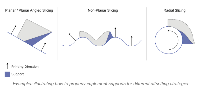
One of the key advantages of robotic arm metal 3D printing is its ability to minimize the use of supports due to its increased degrees of freedom. This allows for the generation of toolpaths that can be adapted to complex geometries. Nonetheless, there are situations where it becomes necessary to evaluate the use of supports or modify the toolpath to accommodate such complicated designs.
In some cases, incorporating a small amount of additional material that can be easily machined afterward may prove more advantageous than attempting to adapt the toolpath to highly complex geometries. This approach prevents potential instability issues that may arise if the process parameters are not meticulously defined. By strategically introducing supplementary material that can be later removed, the overall printing process can be optimized for stability and efficiency.
It is important to note that the decision to add support depends on the chosen toolpath generation strategy. Regardless of the strategy employed, all supports must be implemented by offsetting the surface during the slicing process, with the exception of pipes or revolved surfaces.
Printing Volume
When it comes to the printing volume, the only constraint is the working range of the robotic arm. Meltio’s deposition head is a versatile and independent tool that seamlessly integrates with a diverse range of robot brands. This integration ensures that the robot arm itself becomes the sole determinant of the printing volume, eliminating any additional limitations in terms of size
TIP: Discover the Meltio Engine Robot, the perfect platform for large and complex 3D printing, repair, cladding, and feature addition.


