
Conformal cooling channels refer to cooling channels that are designed to conform to the shape of a part being manufactured and therefore not possible to produce with traditional manufacturing methods. These cooling channels are typically used in molds for polymer injection molding and in a variety of dies and tools operating at high temperatures.
During injection molding, the plastic material is injected into a mold cavity and allowed to cool and solidify.
Conformal Cooling channels
Conformal cooling channels are designed to follow the contour of the mold cavity. By placing the cooling channels in close proximity to the mold surface, and therefore to the part being manufactured, heat can be removed more quickly and effectively, reducing the cycle time of the manufacturing process.
Conformal cooling channels can also improve the overall quality of the final part by helping to prevent defects such as warpage and sink marks, as well as reducing the risk of thermal fatigue and cracking in the mold itself. The use of conformal cooling channels requires specialized design and manufacturing techniques, such as 3D printing, and the benefits can be significant in terms of improved part quality, reduced cycle times and increased productivity.
Cooling channels geometry and design
The first step in the process is to design the part with the cooling channels using a CAD software. The cooling channels are typically integrated into the design of the part and follow the contour of the part’s surface.
The choice of cross-sectional shape for conformal cooling channels can depend on a variety of factors, including the specific application and the geometry of the part being manufactured. Ultimately, the choice of cross-section for conformal cooling channels will depend on the specific requirements of the application and the size and geometry of the part in order to create an effective cooling system.
2.1. Teardrop shape
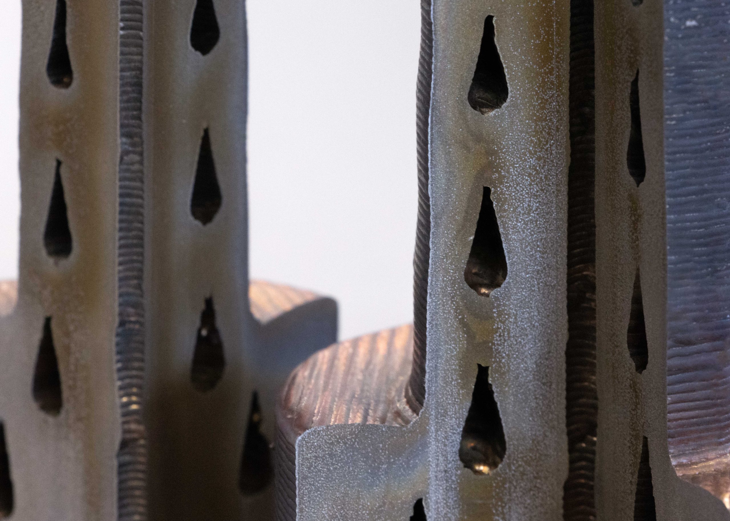
Circular cooling channels not perpendicular to the build plate, cannot be reliably printed since a round profile forms a very steep overhang and bridge at the top. The teardrop shape reduces the maximum overhang angle to a manageable degree.
Teardrop-shaped cooling channels are typically wider at the bottom and narrower at the top, with a rounded edge at the wider end and a pointed edge at the narrower end. This shape allows for a large surface area for heat transfer while maintaining a thin wall thickness and minimizing the amount of material used.
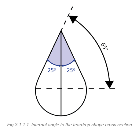
Designing a teardrop shape that can be printed effectively requires careful consideration of its angle relative to the central vertical axis. In order to ensure proper printability, the teardrop shape should have an angle of 25 degrees or less with respect to the central vertical axis that coincides with its midline. When considering the horizontal axis, the angle should be 65 degrees or greater.
A teardrop shape with an angle greater than 25 degrees from the vertical axis may be difficult to print or may require additional support structures. In general, a smaller angle will result in a more easily printable shape.
It is also important to consider other design factors when using teardrop-shaped cooling channels, such as the spacing between channels, the thickness of the walls which should be at least 2.0 mm (the minimum wall thickness printable with Meltio’s technology). These factors can all impact the performance of the cooling system and the manufacturability of the part.
 Once the model with the cooling channels is designed, it needs to be imported as a mesh file into the slicing software. All the features of the channels will be in this single file.
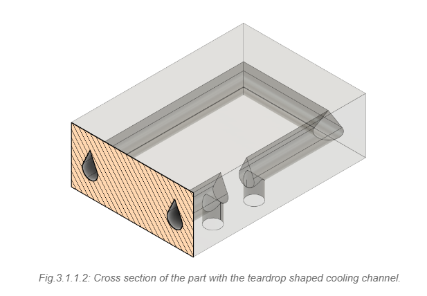
2.2. House shape
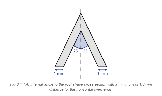
As the name suggests, these channels have a cross-sectional shape that resembles a house, with a peaked roof and angled walls.
The house-shaped cooling channel design can be effective because the angled walls create turbulence in the coolant flow, increasing heat transfer efficiency. The peaked roof of the channel also provides additional surface area for heat transfer. Nonetheless, an improper design or printing parameters can result in reduced cooling efficiency or other defects in the final part.
The house-shaped cooling channels may be more difficult to print than simpler shapes like teardrop-shaped channels. The angled walls and peaked roof of the channels can create overhangs and therefore, the same consideration for the teardrop section should be taken into account: an angle from the vertical middle axis of 25 degrees or less in order to preserve printability.
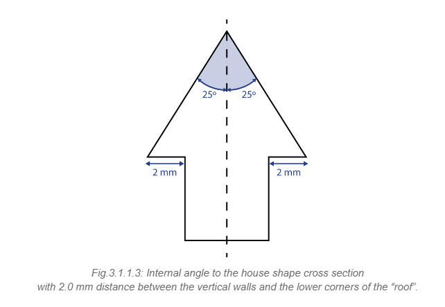
Besides drawing the house-shaped cross section for the cooling channel, it is necessary to draw a CAD model shaped like a house roof. The recommended way to draw this component is by doing an offset of the cooling channel top towards the central vertical axis, considering the same internal axis. The offset distance should be half of the distance between the vertical walls and the lower corners of the “roof” and it must be at least 1.0 mm.
 Once these two cross sections are turned into 3D components by following the established cooling channel’s path, the final part itself needs to be combined with the cooling channel in order to generate the channel cavity.
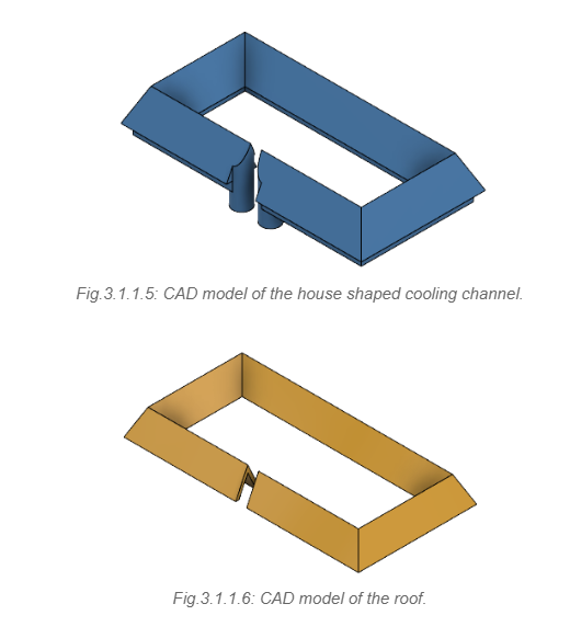
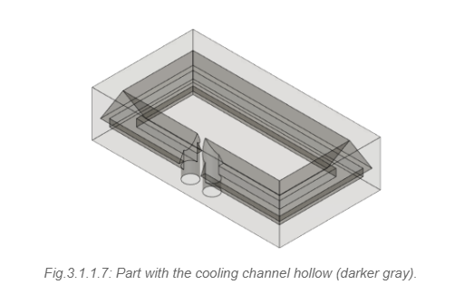
In the assembly, the roof is actually fitting inside the cooling channel, as can be seen in the cross-section below.
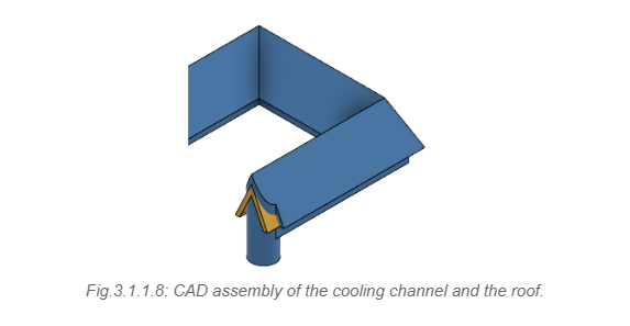 In the slicer software, the part with the cooling channel’s cavity and the roof should be imported as separated mesh files to enable the application of specific printing parameters for each component.
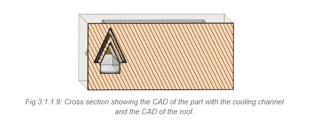
2.3. Squared shape
Square-shaped cooling channels are often used in cooling systems for various applications, including electronic devices, engines, and industrial machinery.
One advantage of using square-shaped channels is that they can provide more surface area for heat transfer compared to circular or other shapes. However, there are also some drawbacks to using square-shaped channels since they can be more difficult to manufacture than circular channels, and they may be more prone to developing stress concentrations at the corners, which can lead to crack square-shaped over time.
To have a squared-shaped cooling channel, the most complicated task is to print the top face of the square since it consists of a bridge between two walls. Therefore, it is necessary to draw the top face in a specific way to guarantee its printability. 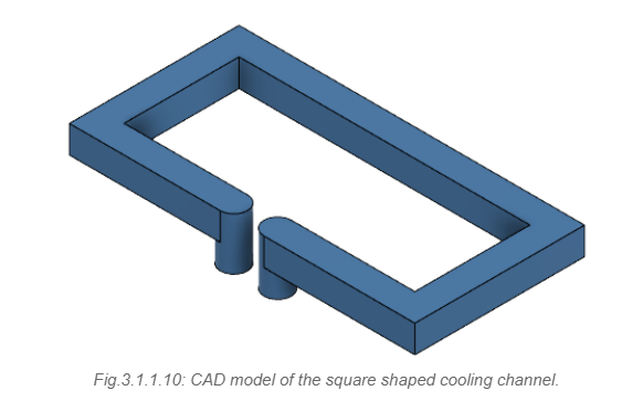 To close the square-shaped cooling channel, it is necessary to use the two consecutive printing layers with specific parameters. When creating the cover in the CAD software, it is recommended to add an offset of 2.0 to 3.0 mm around the cooling channel’s top view perimeter. This requires a 2.0 mm tall extrusion, as the layer height used is 1.0 mm, resulting in the possibility of applying these parameters over two layers.
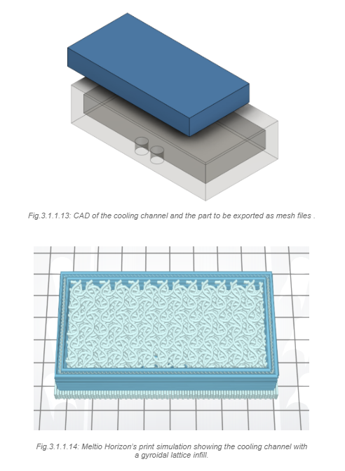
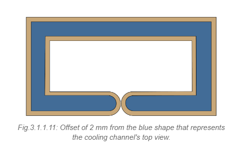 Once the cooling channel has been drawn following the recommendations, it is necessary to export the main part with the channel’s cavity and its ceiling as separate mesh files. This is required to apply specific printing parameters to this component, which will be discussed in the next chapter.
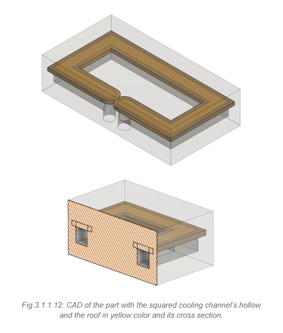
2.4. Gyroidal lattice infill
Gyroidal lattice infill is a type of 3D printing infill pattern that consists of a repeating, porous lattice structure. This lattice structure can be used to create conformal cooling channels in 3D-printed parts.
The gyroidal lattice infill pattern is particularly well-suited for use in conformal cooling channels because of its ability to create a complex, interconnected network of channels that can efficiently remove heat from the part. The lattice structure is made up of interlocking, curved channels that provide a large surface area for heat transfer while maintaining structural integrity.
Using a gyroidal lattice infill for cooling channels can provide a lot of flexibility in terms of the geometry and shape of the channels. By incorporating a gyroidal lattice infill into the design of a cooling channel, it is possible to create channels with complex and unconventional shapes. Thus, a cooling channel using a gyroidal lattice infill can match the part’s shape without issues and follow its contours, without the need for additional support structures.
TIP: If you want to know more about how cooling can help and improve your manufacturing capabilities, download the full whitepaper for free.
This can allow for greater design flexibility and customization, as well as improved cooling performance by optimizing the shape and size of the channels to match the specific cooling requirements of the application. Another advantage of using gyroidal lattice infill for cooling channels is that it can be easily integrated into the overall design of the part, eliminating the need for additional components or assembly steps. This can help to reduce the overall cost and complexity of the manufacturing process.
However, it is important to carefully consider the design and printing parameters when using gyroidal lattice infill for cooling channels, as improper design or printing parameters can result in reduced cooling efficiency or lead to other defects in the final part.
Meltio Horizon slicer offers a new infill strategy for Gyroid Lattice to generate parts with defined open cell porosity. In combination with the Object modifiers, it is easy to define a central region of the build and apply different hatching strategies based on model overlap. There is no need to be concerned about having a solid model with a gyroid lattice in the CAD software because it can be implemented directly in the slicer software.
By utilizing Meltio Horizon, the part with the cooling channel’s cavity and the solid model of the cooling channel volume should be imported as individual mesh files. Then, the Gyroid Lattice infill can be selected as the infill pattern for the cooling channel whilst a linear infill can be used for the part. Having these two components in the slicer software allows the application of the specific printing parameters for each component.
G-code Settings and Printing Parameters
The printing parameters are the various settings and configurations that are used in the printing process to control the behavior of the 3D printer. These settings include factors such as layer height, infill density, print speed, laser power, and more. The choice of appropriate G-code settings and printing parameters can have a significant impact on the quality, speed, and reliability of the printing process, as well as the overall performance of the final product.
When printing cooling channels, the following parameters are critical to ensure their effectiveness and proper functionality.
1. Layer height: The layer height determines the resolution of the printed part and can affect the accuracy of the cooling channel’s dimensions. A smaller layer height can produce a more accurate and precise channel.
For the cooling channel’s top, the layer height must be 0.8 mm or 1.0 mm.
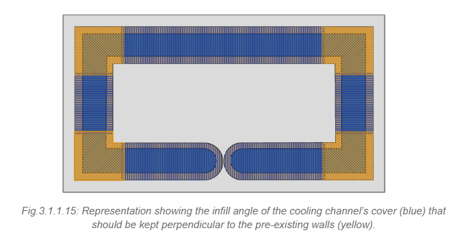
2. Internal infill angle: The angles that are formed between the infill lines inside a 3D-printed object. Infill is the material that fills the inside of a 3D-printed object to provide support and stability. The angle of the infill lines can have a significant impact on the strength and durability of the printed object.
The cover layers of the cooling channels must have the infill angle set in a way that the toolpath will be perpendicular to the preexisting walls that will support it. That way, each line will have a pre-existing structure to start and finish its printing.
3. Outline Overlap: The amount of overlap between adjacent printed outlines (perimeters) of the 3D model. The Outline Overlap setting determines how much the perimeters will overlap each other as they are printed, which can affect the overall quality and strength of the printed object.
A higher Outline Overlap setting will result in better adhesion between the perimeters and a stronger overall structure. Specifically for the layers that will be closing the cooling channels, the value should be set as 99.0% in order to compensate for the lack of perimeter usage.
4. Infill density: It determines the amount of material used to fill the space between the printed layers. A higher infill density can increase the strength and durability of the printed part, but it can also reduce the cooling channel’s effectiveness.
For cooling channels with gyroidal lattice infill, this parameter should be set within a range of 20.0% to 22.5%. Lower infill densities are generally preferred for cooling channels to maximize their functionality.
5. Laser power: The laser power determines the amount of energy delivered to the wire and substrate, affecting the melt pool size and depth. A higher laser power can increase the melt pool size and deposition rate, but it can also increase the risk of defects or distortion.
For printing the layers directly over the cavity of the cooling channel, ergo the cooling channel ceiling, the laser power must be reduced to a range from 225 W to 275 W. Generally, a laser power of 250 W should work well for this purpose.
6. Printing speed: The printing speed is a major parameter since to be able to print over a gap in order to close the cooling channel it is necessary to substantially reduce the speed.
The printing speed should be set in the slicer software within a range of 100 mm/min to 300 mm/min. In the printer, the print speed can be maintained at 100%.
7. Flow Factor Infill (Deposition feed rate): It determines the rate at which the wire is melted and deposited onto the part. A higher wire feed rate can increase the deposition rate, however, it can also increase the risk of inconsistent deposition.
To compensate for the printing speed reduction, it is necessary to increase the feed deposition rate by about 40% compared to the value used for the other areas of the component. While the rule of thumb can provide a general guideline, the actual value of the parameter will depend on the size and geometry of the part being printed.
8. Process control: It is a system developed by Meltio that adjusts the feed rates in real time to avoid possible failures in the printing process. It detects when there is a lack of continuity in the melt pool (a lack of material) and fills the empty spot, accurately increasing the feed speed while discontinuity is detected.
The process control needs to be set as disabled to print the cooling channels’ ceiling in order to avoid the printing power and the deposition speed automatically increasing since there is actually a lack of material that corresponds to the cooling channel gap.
9. Hot Wire: The hot wire is a system designed to increase the printing speed of the system by preheating the material before it enters the melt pool. The system works by passing a large current from the deposition head through the un-molten wire to the build-plate which is grounded. As the welding wire has the highest electrical resistance within the circuit it heats up preferentially.
The Hot Wire should be set within a range of 2 A to 5 A for printing the layers covering the cooling channels.
10. Print bed temperature: The print bed temperature can affect the adhesion of the printed part to the print bed, which can affect the quality of the cooling channels. A higher print bed temperature may be necessary for certain materials to ensure proper adhesion, but it can also increase the risk of warping or other print defects.
Printing a raft is a common technique used to preheat the print bed and ensure good adhesion between the first layer of the print and the print bed. A raft provides a larger surface area for the first layer of the print to adhere to, reducing the risk of warping, lifting, or other issues that can occur when the first layer does not adhere well to the print bed.
Additionally, preheating the print bed with a raft can help to maintain a consistent temperature across the print bed, resulting in more consistent and accurate prints.
TIP: If you want to know more about how cooling can help and improve your manufacturing capabilities, download the full whitepaper for free.