

Fewer welds, same cost: metal 3D printing a water treatment part


Machine Fabriek Geurtsen builds machines in Deventer, in the east of the Netherlands. Its customers work in defense, packaging and construction, among other sectors, and most of what leaves the shop is custom equipment made in small numbers. One of those machines is a separator for the water treatment industry. Spinning at high speed, it pulls sludge, sand and other sediment out of wastewater so the water can move on to the next stage of cleaning.
Inside that separator sits a part the Dutch team calls the slijtbus versnellingskamer, the wear bush of the acceleration chamber. It is a cone with a flange and six “teeth”, and it takes a beating from abrasive water every hour the unit runs. For years Geurtsen built it the only way the shop floor allowed: by cutting, bending and welding several pieces of stock into one.
That method worked, but it ate welding and machining hours, and the welds inside the cone were the hardest ones to get right. So Geurtsen went to K3D, a production service built around metal additive manufacturing and one of Meltio’s trusted partners, with a clear brief: keep the price competitive and make the part much simpler to produce. The answer turned out to be metal 3D printing for water treatment equipment, using wire-laser metal deposition on an industrial robot.
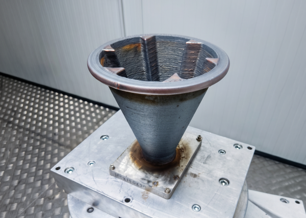
Geurtsen went to K3D with a clear brief: keep the price competitive and make the part much simpler to produce. The answer turned out to be metal 3D printing for water treatment equipment, using wire-laser metal deposition on an industrial robot.
1. Too many welds for one wear bushing
The original wear bush was a weld assembly built from sheet metal and milled bar. A fabricator bent a sheet into a cone, welded a flange onto it, welded six teeth in place and then fitted the whole piece onto a larger cone. Every step needed its own setup, its own stock material and its own operator time.
For a one-off or a short run, that adds up fast. Geurtsen makes this part in low volumes and to custom requirements, so there is no long series to spread the setup cost over. Each new bushing meant repeating the same chain of cutting, forming, welding and machining, with several different materials coming together in one component.
Quality was the other worry. More welds mean more places where something can go wrong, and the joints on the inside of the cone were the ones that mattered most and were hardest to reach. Geurtsen also wanted a part that simply looked better, a cleaner piece of equipment to hand over to its own customer. The goal was a simpler process and a better part, without paying more for it.
2. Why the geometry resisted a simple fix
The wear bushing is not a shape that suits a single conventional process. It combines a vertical shaft section, a long conical body and a flat flange, and the teeth sit on the cone itself. Machining it from solid would mean removing most of a large billet. Casting a low-volume custom part means paying for a pattern that may only ever be used a few times. Fabrication, the route Geurtsen already used, needs welds at every transition.
Additive manufacturing brings its own constraints. A wire-laser deposition head builds material layer by layer, and the toolpath has to follow the geometry without leaving overhangs it cannot support. A cone that flares outward and a flange that sticks out at right angles both push against what a single flat slicing strategy can print.
Tolerances added a final layer. Some surfaces on the top and bottom of the part needed a tight fit with the rest of the separator. A wire-DED part comes off the machine near-net-shape, so those faces would still have to be machined, and the design had to leave enough material there to do it.


3. Three toolpath strategies, one printed part
K3D printed the wear bushing with a Meltio Engine integrated on an industrial robot, using wire-laser metal deposition (W-LMD). The process feeds metal welding wire into a melt pool formed by several lasers and builds the part layer by layer. K3D chose Meltio for two reasons, as it states plainly: material availability and the print size the robot setup makes possible. Because the feedstock is standard welding wire, the shop can source it like any other consumable, and on a robot arm the build volume is set by the robot’s reach rather than a closed chamber.
The project started with design, and it was a joint effort. K3D and Geurtsen worked together to steer the geometry toward something that met every requirement of Geurtsen’s end customer and could still be printed within the limits of the process. Where the separator needed tight fits, on the top and bottom faces, the team added thicker features to give enough stock for machining afterwards.
The build itself used three strategies from Meltio’s toolpath options, each matched to one region of the part:
- Planar Horizontal for the shaft, building flat layers from the base up.
- Conical for most of the geometry, so the layers follow the cone instead of stepping out at every level.
- Radial 360 for the flange, which made a feature that projects outward from the body feasible to print.
Switching strategies inside one build is what let a single print cover a shape that combines a shaft, a cone and a flange. K3D printed the part in SS316LSi, a stainless steel welding wire, with custom process settings it developed in-house.
The project figures are simple. Development, including the joint design work, took two weeks. Printing took 30 hours. Once the part arrived at Geurtsen, the team machined the critical top and bottom surfaces to the required tolerances in its own shop, closing a hybrid workflow that pairs near-net-shape deposition with conventional finishing.
The project figures are simple. Development, including the joint design work, took two weeks. Printing took 30 hours. Once the part arrived at Geurtsen, the team machined the critical top and bottom surfaces to the required tolerances in its own shop, closing a hybrid workflow that pairs near-net-shape deposition with conventional finishing.
4. Less welding, better results, same cost
Geurtsen’s verdict on the project is direct: better results without increasing costs. That matches the brief it gave K3D at the start: a simpler process at a competitive price, and it rests on a few concrete changes.
Fewer welding and machining hours
Printing the geometry replaces most of the cutting, bending and welding that the old assembly needed, and machining is limited to the faces that need a tight fit.
Lower risk of errors
Each weld in the old assembly was a chance for a defect. Geurtsen reports that the printed route minimizes that risk, with the biggest gain on the inside of the cone, where manual welding was hardest to do well.
A cleaner part
Improving the look of the component was one of Geurtsen's goals, and the printed bushing replaces a visibly fabricated assembly.
Fast development for a custom part
Two weeks from joint design to a printable part, then 30 hours of printing, is a short loop for a low-volume component with no tooling involved.
One material instead of several
The old part combined different stock materials. The new one is built in a single stainless steel wire, SS316LSi.


5. What a printed wear bushing says about fabricated parts
For Geurtsen, the wear bushing is now a part it can order with a simpler process behind it and finish in its own shop. The next steps the project points to are the same ones that drove the project: keep simplifying how the part is made and keep raising its quality, especially inside the cone where hand welding used to decide the result.
The wider lesson is about a type of part that every machine builder knows. Plenty of equipment still relies on components fabricated from sheet and bar because nothing else made sense at low volume. When the geometry can be printed close to final shape in a single weldable wire, with machining only where the fit demands it, the weld assembly stops being the default.
That is the shift Meltio sees across industrial users of wire-laser metal deposition, from proving a part can be printed to making it part of normal production. K3D’s view that the technology suits long series as well as one-offs points the same way. In a separator that cleans wastewater, it starts with one bushing.
FAQs
Yes, when the geometry can be printed close to final shape. K3D replaced a wear bush that Machine Fabriek Geurtsen used to build from bent sheet metal, a welded flange, six welded teeth and milled bar with a part printed by wire-laser metal deposition. Geurtsen reports fewer welding and machining hours and a lower risk of errors, at no extra cost.
The wear bush was printed in SS316LSi, a stainless steel welding wire. K3D developed custom process settings for it in-house. Using one wire replaced the several stock materials that went into the original welded part.
Development took two weeks and printing took 30 hours. The two weeks covered joint design work between K3D and Geurtsen to meet the end customer's requirements and the limits of the printing process. Machining time at Geurtsen was not disclosed.
K3D used a Meltio Engine integrated on an industrial robot. The Meltio Engine turns a robot arm into a wire-laser metal deposition system. K3D chose Meltio for the material availability of welding wire and the print size the robot setup allows.
Yes, on surfaces that need a tight fit. Wire-laser metal deposition produces near-net-shape parts, so the design adds extra stock where tolerances are critical. On this wear bush, Geurtsen machined the top and bottom surfaces after printing.
The system uses welding wire rather than metal powder, which fits well with TNB Remaco's existing welding and fabrication capabilities.
You combine several toolpath strategies in one build. K3D printed the shaft with a Planar Horizontal strategy, most of the cone with a Conical strategy and the flange with a Radial 360 strategy. Matching the strategy to each region made the full geometry printable in a single part.